
 One of the issues I have is that the mount location on the Getrag is around 50mm forward in car line to the foremost mounting hole welded to the chassis.
So a bespoke plate is going to be needed to make up the gap and fix to the bottom of the Energy Suspension mount.
 Luckily the mount exactly matches the getrag bolt spacing so thats a bit of luck!
With the mount in place I fixed a card template to the chassis and started the mock up process. In the end I took various measurements from the chassis holes and used the chassis cross member behind the mounting wings as a datum.

Knowing the mount holes centres I then entered the whole thing into AutoCAD, played around a bit, printed it out 1:1 and made V1 MDF template.

With this fitted I noted that I could not get a socket on to the mount bolts, this is required as there is a bit of jiggling about require to get all the bolt holes lined up before all the bolts can be located and tightened due to the slots in the mount.
 So I modified the template to give access.
With the mount all fitted and OK I returned to the computer and made the final changes, spent ages working out how to apply dimensions, made a drawing block template and voila finished drawing.
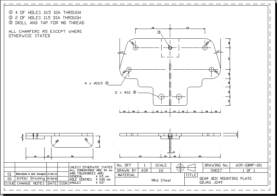 I also added the 8mm threaded hole for the exhaust mount and a strengthening rib under the plate as the gearbox mounts outside of the chassis bolt locations.
I should at this point offer major thanks to Simon for his help with drawing standards and advice. - Cheers mate!
The bracket is now out with PJO Engineering in Swindon for Manufacture.
No comments:
Post a Comment