Confirmed last week that the gearbox brackets should be ready on Friday, once thats done the clutch bracket goes for manufacture (if the mount brackets are good) and I can sort out the gearshift extension.
Had a good chat with Andy at GD on Friday to sort out a few options and I think I have decided now to fit the anti roll bar now instead of waiting unti lthe car is finished! Just need to work out if it will fit over the water pump pully.

Sunday, 9 May 2010

Friday, 30 April 2010
Progress...?
Well the engineering firm has found my drawings and promised to start next week..... Watch this space!
Monday, 26 April 2010
Friday, 26 March 2010
Gear box mount spacer
One thing I neglected to do was level the gearbox! So with jack under the box (not in the box....ah well Ill get my coat!)
I realised I need a 22 mm spacer between the mount and the gear box. This will also solve the issue of clearnace between the mount and the gearbox itself.
 Again some AutoCAD work and the drawing was ready, its with PJO as well!
I realised I need a 22 mm spacer between the mount and the gear box. This will also solve the issue of clearnace between the mount and the gearbox itself.
 Again some AutoCAD work and the drawing was ready, its with PJO as well!
Gear box mount.
A few bits of wood are all very nice but I cant see them being a permanent solution!
 One of the issues I have is that the mount location on the Getrag is around 50mm forward in car line to the foremost mounting hole welded to the chassis.
So a bespoke plate is going to be needed to make up the gap and fix to the bottom of the Energy Suspension mount.
 Luckily the mount exactly matches the getrag bolt spacing so thats a bit of luck!

With the mount in place I fixed a card template to the chassis and started the mock up process. In the end I took various measurements from the chassis holes and used the chassis cross member behind the mounting wings as a datum.

Knowing the mount holes centres I then entered the whole thing into AutoCAD, played around a bit, printed it out 1:1 and made V1 MDF template.

With this fitted I noted that I could not get a socket on to the mount bolts, this is required as there is a bit of jiggling about require to get all the bolt holes lined up before all the bolts can be located and tightened due to the slots in the mount.
 So I modified the template to give access.

With the mount all fitted and OK I returned to the computer and made the final changes, spent ages working out how to apply dimensions, made a drawing block template and voila finished drawing.
 I also added the 8mm threaded hole for the exhaust mount and a strengthening rib under the plate as the gearbox mounts outside of the chassis bolt locations.
I should at this point offer major thanks to Simon for his help with drawing standards and advice. - Cheers mate!
The bracket is now out with PJO Engineering in Swindon for Manufacture.
 One of the issues I have is that the mount location on the Getrag is around 50mm forward in car line to the foremost mounting hole welded to the chassis.
So a bespoke plate is going to be needed to make up the gap and fix to the bottom of the Energy Suspension mount.
 Luckily the mount exactly matches the getrag bolt spacing so thats a bit of luck!
With the mount in place I fixed a card template to the chassis and started the mock up process. In the end I took various measurements from the chassis holes and used the chassis cross member behind the mounting wings as a datum.

Knowing the mount holes centres I then entered the whole thing into AutoCAD, played around a bit, printed it out 1:1 and made V1 MDF template.

With this fitted I noted that I could not get a socket on to the mount bolts, this is required as there is a bit of jiggling about require to get all the bolt holes lined up before all the bolts can be located and tightened due to the slots in the mount.
 So I modified the template to give access.
With the mount all fitted and OK I returned to the computer and made the final changes, spent ages working out how to apply dimensions, made a drawing block template and voila finished drawing.
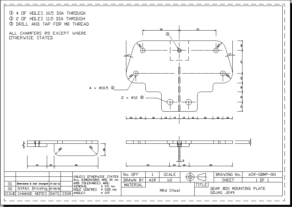 I also added the 8mm threaded hole for the exhaust mount and a strengthening rib under the plate as the gearbox mounts outside of the chassis bolt locations.
I should at this point offer major thanks to Simon for his help with drawing standards and advice. - Cheers mate!
The bracket is now out with PJO Engineering in Swindon for Manufacture.
Tuesday, 23 February 2010
Clutch fork mods.
Now the engine was in I could start to look at some of the little jobs that need doing. the first of which was to check that the clutch fork would clear the chassis.
I has already removed the 2 points from the end of the fork to give greater clearance, but looking at it in situ I decided that the return spring hole had to go as well.

So out with the trusty dremel and about half an hour later the fork was modified, this is as far as I can go without the slave to move the clutch and check clearance.
 Next step on the clutch is finalise the slave bracket design and get it built!
I has already removed the 2 points from the end of the fork to give greater clearance, but looking at it in situ I decided that the return spring hole had to go as well.

So out with the trusty dremel and about half an hour later the fork was modified, this is as far as I can go without the slave to move the clutch and check clearance.
 Next step on the clutch is finalise the slave bracket design and get it built!
Sunday, 21 February 2010
Engine update....
IT FITS!!!!!!
Well stone me, it went it in without too many protestations. We had a little bit of mucking about with the engine mounts but eventually she was in. To top it off the gearbox appears to fit OK as well!


Many thanks to Andy J and "its not a cravat!" Malcom T.
Well chuffed!
Well stone me, it went it in without too many protestations. We had a little bit of mucking about with the engine mounts but eventually she was in. To top it off the gearbox appears to fit OK as well!


Many thanks to Andy J and "its not a cravat!" Malcom T.
Well chuffed!
Well todays the day - hopefully!
There no more time to mess about with tape measures and bits of wood, its time to see if the engine and gearbox will fit in the chassis.
As I appear to be the only person as yet known who has fitted a Getrag gearbox in a GD I may be about to find out why everyone else pays the extra and buys a Tremec! My main aeas of concern are.
1) Gearbox rear mount location relationship to the GD mount tabs.
2) Clutch fork interference with chassis rails and body.
3) Clutch slave bracket interference with chassis rails.
To be honest item 1 could probably be worked around but 2 and 3 may well be deal breakers. So by 18:00 today I will either my very happy with some nice pics to show or very sad with a Getrag gearbox up for sale!!
Watch this space....
There no more time to mess about with tape measures and bits of wood, its time to see if the engine and gearbox will fit in the chassis.
As I appear to be the only person as yet known who has fitted a Getrag gearbox in a GD I may be about to find out why everyone else pays the extra and buys a Tremec! My main aeas of concern are.
1) Gearbox rear mount location relationship to the GD mount tabs.
2) Clutch fork interference with chassis rails and body.
3) Clutch slave bracket interference with chassis rails.
To be honest item 1 could probably be worked around but 2 and 3 may well be deal breakers. So by 18:00 today I will either my very happy with some nice pics to show or very sad with a Getrag gearbox up for sale!!
Watch this space....
Sunday, 14 February 2010
Clutch slave.
With things dried out in the garage (£93 worth of electricity later!!) I need to press on and get the clutch slave cylinder bracket sorted. This needs to be done before the engine goes into the chassis as space will be tight and its much easier to work around the engine on the floor stand.
I need to get the engine into the chassis to make way for my next side project, Ive a Ford Pop engine to rebuild for my father in law so I need the space currently occupied by my engine. I did offer him the 302 but he felt it a little over powered fro the Pop!
Of course this being my build nothing goes simply or follows the accepted norm. Whereas most would buy the Tremec gearbox option and have the joy of using the Repower slave cylinder and bracket that just bolts on, I of course chose the little used Getrag/Ford in a GD combination. A such a slave cylinder and bracket are not available off the shelf in a kit, but hey its all good fun and I'm saving money, well that's what I keep telling myself!
The clutch fork on the standard Ford setup operated the opposite way to a Tremec in that the cylinder needs to be engine side and push to the rear of the car, of course engine side is where the bell housing is and space is a little tight.
I will go back and populate with pics in the future of the various designs I wen through but here's V2 that has now been sidelined in favour of V3 which is under development.


 As you can see it is mocked up in MDF and once finalised I will transfer to AutoCAD and get them cut from mild steel in 6mm thickness (thanks Simon for that advice).
having looked at the design I am now trying to work out if I can out the vertical mounting plate on the other side close to the bellhousing thus reducing the width of the assembly by about 8-10mm.
Back to the drawing board.
I need to get the engine into the chassis to make way for my next side project, Ive a Ford Pop engine to rebuild for my father in law so I need the space currently occupied by my engine. I did offer him the 302 but he felt it a little over powered fro the Pop!
Of course this being my build nothing goes simply or follows the accepted norm. Whereas most would buy the Tremec gearbox option and have the joy of using the Repower slave cylinder and bracket that just bolts on, I of course chose the little used Getrag/Ford in a GD combination. A such a slave cylinder and bracket are not available off the shelf in a kit, but hey its all good fun and I'm saving money, well that's what I keep telling myself!
The clutch fork on the standard Ford setup operated the opposite way to a Tremec in that the cylinder needs to be engine side and push to the rear of the car, of course engine side is where the bell housing is and space is a little tight.
I will go back and populate with pics in the future of the various designs I wen through but here's V2 that has now been sidelined in favour of V3 which is under development.


 As you can see it is mocked up in MDF and once finalised I will transfer to AutoCAD and get them cut from mild steel in 6mm thickness (thanks Simon for that advice).
having looked at the design I am now trying to work out if I can out the vertical mounting plate on the other side close to the bellhousing thus reducing the width of the assembly by about 8-10mm.
Back to the drawing board.
Wednesday, 13 January 2010
Bit of a set back.
Well, Christmas over. Time to move on into 2010.
What a great start to the year, 3 popped 15mm compression joints and my garage is flooded to a depth of 1", amazing how well the garage door seals!
So Ill be drying things out for a while yet I think. Boo!
What a great start to the year, 3 popped 15mm compression joints and my garage is flooded to a depth of 1", amazing how well the garage door seals!
So Ill be drying things out for a while yet I think. Boo!
Bit of a set back.
Well, Christmas over. Time to move on into 2010.
What a great start to the year, 3 popped 15mm compression joints and my garage is flooded to a depth of 1", amazing how well the garage door seals!
So Ill be drying things out for a while yet I think. Boo!
What a great start to the year, 3 popped 15mm compression joints and my garage is flooded to a depth of 1", amazing how well the garage door seals!
So Ill be drying things out for a while yet I think. Boo!
Thursday, 24 December 2009
Merry Christmas..
Well another year draws to an end and despite everything thats been going, and against my previous expectations, I have managed to make some progress this year.
Granted its nowhere near where Id hoped to be if you had asked me in the middle of 2008, but all things considered Im happy to have made progress and to be honest even happier that I still have the Cobra.
So I wish everyone whos been reading my antics a very Happy Christmas and a prosperous new year for 2010.
You never know maybe there will be a few updates soon!
Bye for now.
Granted its nowhere near where Id hoped to be if you had asked me in the middle of 2008, but all things considered Im happy to have made progress and to be honest even happier that I still have the Cobra.
So I wish everyone whos been reading my antics a very Happy Christmas and a prosperous new year for 2010.
You never know maybe there will be a few updates soon!
Bye for now.
Saturday, 3 October 2009
Moly applied.
With a little time available I pressed on and applied the Molybdenum Disulphide spray.
Everything was cleaned thoroughly to remove traces of oil / grease etc and makes off the make sure areas which didn't want to be sprayed were not.
In the bellhousing I sprayed the input shaft outer tube, input shaft and pilot bearing shaft. Also I gave the top of the fork pivot a coat to help things there.
 Other parts coated were the reverse side of the release bearing, rotating section of the release bearing where it touches the diaphragm springs and the inner bore of the release bearing.
The clutch fork in the pivot area and the tips were it bears on the release bearing.
 Hopefully this will keep things moving well for sometime.
All that remains to be done now is to wait for the coating to cure, 3 + hours, and burnish lightly with a lint free cloth to improve the surface finish.
One final job I did tonight was to fill the diff with oil, been meaning to do this for a while so now its done. I jacked the rear up and spun the wheels round to get the oil moving in the diff, its been sat for quite a while now.
Everything was cleaned thoroughly to remove traces of oil / grease etc and makes off the make sure areas which didn't want to be sprayed were not.
In the bellhousing I sprayed the input shaft outer tube, input shaft and pilot bearing shaft. Also I gave the top of the fork pivot a coat to help things there.
 Other parts coated were the reverse side of the release bearing, rotating section of the release bearing where it touches the diaphragm springs and the inner bore of the release bearing.
The clutch fork in the pivot area and the tips were it bears on the release bearing.
 Hopefully this will keep things moving well for sometime.
All that remains to be done now is to wait for the coating to cure, 3 + hours, and burnish lightly with a lint free cloth to improve the surface finish.
One final job I did tonight was to fill the diff with oil, been meaning to do this for a while so now its done. I jacked the rear up and spun the wheels round to get the oil moving in the diff, its been sat for quite a while now.
Wednesday, 23 September 2009
Clutch build up
With the bell housing dialled in and the gearbox assembled I moved onto finally assembling the clutch to the engine.
First off I modified the block plate lower starter mounting hole to account for the alignment adjustment made by the offset dowels, Oh and painted the block plate red to match the engine! You can just see here how the heat of running the engine has changed the paint colour, they are both painted from the same can!

 Next I pressed the flywheel dowel pins into place (glad I got that press!) and cleaned the flywheel, paying particular attention to the clutch surface. Oh and also the flywheel bolts and holes in the crank to ensure a good seal.
After a bit of wrestling with the flywheel I got it onto its register on the crank with all the bolt holes lined up. It appears it only fits on in two locations as although the holes look evenly spaced, they are not! Given the weight of the flywheel it wasnt fun battling with it to get it lined up and on!
Now its important to use thread sealer on the flywheel bolts as the crank drillings are open to the sump, as I found out on the dyno oil will work its way past the threads. So Loctite 577 was used as I know it fuel safe so I figured it would also be oil safe!

With the flywheel on the clutch plate was installed on its locating tool and inserted into the pilot bearing.
 Finally the clutch cover was cleaned again to remove a traces of grease/oil and snapped over its dowel pins on the flywheel. The bolts thread locked with loctite and installed finger tight at first then 2-3 turns at a time wound in to bring the cover tight to the clutch plate.
 Final thing tonight was to mount the bell housing to the engine with he clutch fork in place. I just wanted to see how the release bearing was going to sit against the clutch cover.

Luckily it all looks OK, also with the rubber boot on the clutch fork is naturally drawing the release bearing away from the cover so I that's stopped me worrying that the boot would cause the bearing to ride the cover.
First off I modified the block plate lower starter mounting hole to account for the alignment adjustment made by the offset dowels, Oh and painted the block plate red to match the engine! You can just see here how the heat of running the engine has changed the paint colour, they are both painted from the same can!

 Next I pressed the flywheel dowel pins into place (glad I got that press!) and cleaned the flywheel, paying particular attention to the clutch surface. Oh and also the flywheel bolts and holes in the crank to ensure a good seal.
After a bit of wrestling with the flywheel I got it onto its register on the crank with all the bolt holes lined up. It appears it only fits on in two locations as although the holes look evenly spaced, they are not! Given the weight of the flywheel it wasnt fun battling with it to get it lined up and on!
Now its important to use thread sealer on the flywheel bolts as the crank drillings are open to the sump, as I found out on the dyno oil will work its way past the threads. So Loctite 577 was used as I know it fuel safe so I figured it would also be oil safe!

With the flywheel on the clutch plate was installed on its locating tool and inserted into the pilot bearing.
 Finally the clutch cover was cleaned again to remove a traces of grease/oil and snapped over its dowel pins on the flywheel. The bolts thread locked with loctite and installed finger tight at first then 2-3 turns at a time wound in to bring the cover tight to the clutch plate.
 Final thing tonight was to mount the bell housing to the engine with he clutch fork in place. I just wanted to see how the release bearing was going to sit against the clutch cover.
Luckily it all looks OK, also with the rubber boot on the clutch fork is naturally drawing the release bearing away from the cover so I that's stopped me worrying that the boot would cause the bearing to ride the cover.
So thats it, all I need now is the moly spray to treat the input shaft and I think the gearbox assembly can be mounted to the engine!
Saturday, 19 September 2009
Gearbox adapter plate
Now that the gearbox was home and the bell housing alignment sorted I could get on and mount the adpter kit to the bellhousing. Now this is where I should have a picture of the kit parts laid out on the floor, but in my haste to get on and install it, I forgot - sorry!

 The nylon disc fits tightly to the gearbox output shaft, this then also fits tightly inside the bellhousing opening and centres the gearbox to the bell housing.
Kit of parts as supplied by AK sportscars. - Thanks for your help with this.
Roller pilot bearing set in a machined extension.
Machined adapter plate.
Nylon centralising disc
Sleeve welded into my own release bearing (had to send it to AK before the kit was supplied)
1 - fit pilot bearing into the crank
2 - fit disc into bell housing, the odd yellow stuff round the disc is actually double sided tape! The disc was slightly too small for the hole so on AK's advice I wrapped it round once only with tape. (note I also drilled and tapped mine in two places so I could remove it, something Ive decided not to do at this stage)
The nylon disc fits tightly to the gearbox output shaft, this then also fits tightly inside the bellhousing opening and centres the gearbox to the bell housing. Before mounting the bellhousing I applied a layer of RTV silicone to the gearbox face to stick the disc in place.


3 - bolt it all together!
The machined adapter plate bolts to the gearbox and then to the bell housing and thats it!
I could then assembly the release bearing and clutch fork to the fork pivot.
Ive decided to add some form of lubrication to the input shaft where the release bearing will slide, this needs to be dry and the concensus of opinion is to use molybdenum disulphide air dry filmspray.
After a bit of net searching I settled on Rocol 10025, not cheap but I know Mocol products are good and it was the only one listed as not being just for the break in period.
So on to the clutch - really I will this time!!
Friday, 11 September 2009
Gearbox fixed
CTS found the cause of the problem. Apparently a hub spring had "jumped". Not totally sure what that means, but following another 6 hour round trip to Markyate the box is back and now working!
The shift is now much smoother and all gears select fine.
While the box was away I located new reverse and 1st/2nd gear lock out switches. Turns out that although Jaguar have different part numbers for each switch they are actually the same. So after SNG Barrett found that Jaguar had no stock of the lock out switch I just ordered up another reverse switch!
Job done.
The shift is now much smoother and all gears select fine.
While the box was away I located new reverse and 1st/2nd gear lock out switches. Turns out that although Jaguar have different part numbers for each switch they are actually the same. So after SNG Barrett found that Jaguar had no stock of the lock out switch I just ordered up another reverse switch!
Job done.
Friday, 21 August 2009
Finishing off the bell housing.
With the offset dowels to hand it was time to finish off the bell housing. Having figured out where the offset was by rolling the dowels on a flat surface (picture of someones 0.021" dowel)


It might appear like this was a quick and easy process but it wasnt! Each time an adjustment was made the bell had to be torqued up to spec and remeasured. If you take into account the couple of times I knocked the DTI out of position and had to set it all up again and remeasure to confirm correct setting it took about 5 hours in total to get to here. Still, its worth it!

I could then install them into the block. Luckily the original Ford dowels just tapped out with no fuss.
1st attempt didnt go well and I figured out that Id put the dowels in 180deg out!!
2nd attempt looked better with the measurements getting closer to spec.
3rd got closer still.
Finally on the 4th attempt we hit the jackpot and all the measurements fell into spec with a total missaligment of 0.0025"
It might appear like this was a quick and easy process but it wasnt! Each time an adjustment was made the bell had to be torqued up to spec and remeasured. If you take into account the couple of times I knocked the DTI out of position and had to set it all up again and remeasure to confirm correct setting it took about 5 hours in total to get to here. Still, its worth it!
So thats it bell housing correctly aligned to the crank centreline and flywheel face.
Clutch assembly next!
Friday, 14 August 2009
Bellhousing alignment.
The next major part of the drivetrain to sort out is the alignment of the bellhousing.  The engine was rotated and the misalignment read from the dial gauge, the miss alignment was less than 0.0015" and therefore I judged acceptable.
 Step 2

With ths standard Ford dowels it was obvious that the alignment was not good enough.
 With the missalignment measured I need a set of 0.07" offset dowels to shift the whole housing to the right and up a bit.

As the engine is putting out a bit more power than when it left Ford 37 years ago and Im using a selection of bits not really intended to be put together, it is necessary to make sure the gearbox input shaft is in line with the pilot bearing.
The way to do this is to align the bellhousing to the back of the engine and to the crank centreline.
Step 1
Check that the bellhousing rear face is parrallel to the flywheel. To do this on the Ford you need to mount the block plate first, then the flywheel finally the bellhousing.
With sufficient flywheel bolts removed the DTI was mounted and aligned on the rear face of the bellhousing.
The engine was rotated and the misalignment read from the dial gauge, the miss alignment was less than 0.0015" and therefore I judged acceptable. Step 2The next step is to check the alignment of the bellhousing to the crank centreline. To do this the DTI is again mounted to the flywheel but this time the tip is located on the inner register of the flywheel bore.
This time I was looking for a a total miss alignment of no more than 0.005"
With ths standard Ford dowels it was obvious that the alignment was not good enough.
With the missalignment measured I need a set of 0.07" offset dowels to shift the whole housing to the right and up a bit. A quick call to Real Steel and its just a case of waiting for the post.
Monday, 3 August 2009
Gearbox off for rebuild.
Took the gearbox over to CTS today (gearboxman) so hopefully should get that back next week all ready to fit. My next decision is wether to paint it silver or just a clear coat of POR15. Once its back and I can see what its like after its uber clean I can make my mind up.
Ordered all the clutch bits from Real Steel today and will get the adapter kit from AK once the release bearing has arrived. I need to send the bearing to AK for adaptation.
No I need to figure out how you dial in a bell housing.....
So some small progress made.
Ordered all the clutch bits from Real Steel today and will get the adapter kit from AK once the release bearing has arrived. I need to send the bearing to AK for adaptation.
No I need to figure out how you dial in a bell housing.....
So some small progress made.
Wednesday, 8 July 2009
Updated video
Subscribe to:
Posts (Atom)